CAD Modeling
Before generating solid or mesh models, see the tutorial Mechanism in the World Frame which explains how the line model of the mechanisms look like in the backend and how the design parameters can be generated.
Generating CAD Models
There are three methods for exporting the mechanism as a mesh or solid model. The Python libraries
build123d are required for STEP files generation, while
trimesh and manifold3d are required for STL generation. You can install them using pip:
pip install build123d trimesh manifold3d
RationalMechanism.export_single_mesh() returns an STL mesh file of the whole mechanisms. Similarly,
RationalMechanism.export_single_solid() returns a STEP file. In both cases, the mechanism bodies
are merged in a single body. An interactive visualization of the method
RationalMechanism.export_single_solid() STEP file can be seen here:
Alternatively, the method RationalMechanism.export_solids() returns a STEP file that consists of
assembled solids, i.e. the every link is one part (the joints of two links overlap).
When importing in your CAD, keep in mind to import it as assembly.
All methods accept various arguments for customization of the output. For example,
they accept arguments for size of the joints and links cylinders, and also can
add the tool link and frame meshes. Be careful with units (e.g. in RationalMechanism.export_single_solid())
it has to be specified if the result and inputs are in millimeters or meters.
from rational_linkages.models import bennett_ark24

m = bennett_ark24()

m.export_single_mesh(scale=1.0,  # mind that this example will produce a tiny model
                     link_diameter=0.01,
                     joint_diameter=0.02,
                     add_tool_frame=True,
                     file_name='mechanism.stl')

m.export_solids(units="mm",
                link_diameter=10,  # 10 mm if units="mm", otherwise 10 m
                joint_diameter=20,  # 20 mm if units="mm"
                add_tool_frame=True,
                file_name="mechanism.step")
Visualizing Custom STL in MotionDesigner
Any STL file can be imported as solid body in Motion Designer. This can be useful for visualizing the mechanism in the context of the task, e.g., your work-cell.
It is better if the STL file coordinates are already in the world frame
(p0 of your mechanism in MotionDesigner), however you can use the transform argument to place it wherever needed.
Place the STL file in the same directory as your script and use the following pattern:
from rational_linkages import MotionDesigner, TransfMatrix
from rational_linkages.models import cart_stl

md = MotionDesigner(method='quadratic_from_poses',
                    preview_mechanism=True,
                    arrows_length=0.1)
path_to_stl = cart_stl()  # replace with path to your STL, for example:
# path_to_stl = "cart.stl"

# add transform for the mesh if needed
tr = TransfMatrix.from_rpy_xyz([0, 0, -90], [0.23, -0.44, -1.2], unit="deg")

md.add_mesh_from_stl(path_to_stl, scale=1, transform=tr)
md.show()
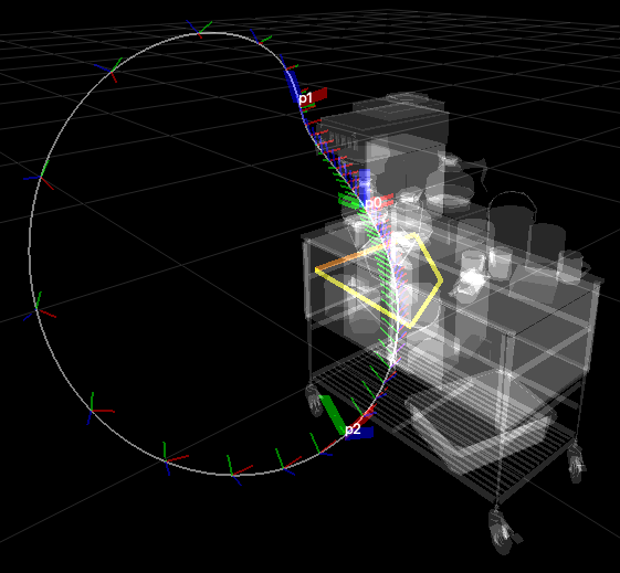
The scene will look similar to the figure above.
As you can notice, argument preview_mechanism is set to True. This will visualize
the mechanism in the MotionDesigner window, so you can check if the size and position of the mechanism is
adequate in the context of your task. However, the previewing has impact on rendering performance. Also,
keep in mind that this design can be changed by dragging the physical connection points along joint axes,
so the preview is supposed to be only informative.